Line Following Robot Project (RGB Integration)
The Problem
The problem was as stated: use your color sensor to autonomously navigate a maze by following a specific color line. Many challenges could be derived from the problem statement, and a few our team tackled are highlighted below:
- Robot that can traverse every line in every color
- Travel one line in one direction and return through another line
- Speed changes based on color line
Criteria for the project:
- One must incorporate the TCS3200 color sensor to obtain data
- One must implement portions of PID controls to move the robot and error check
- It must be done in the basement of the engineering department, with controlled lighting.
The Process
CAD/Manufacturing
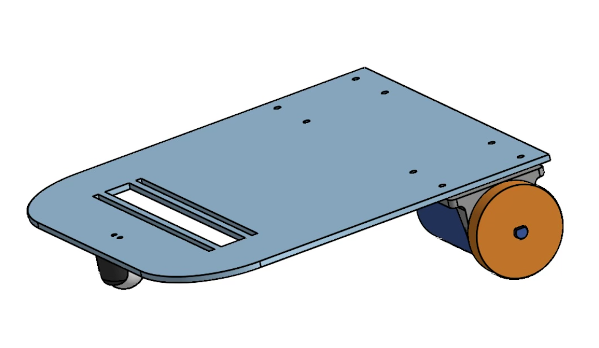
The robot had 4 different parts, each serving a specific purpose:
- Body: The base of the car served as the component that held everything together. This was laser cut and designed with the idea that a color sensor would be positioned in an arbitrary location along the x-axis of the base.
- Motor Mounts: The motor mounts were 3D printed to mount the motor in a specific location along the base. They are symmetrical, and two were printed to accommodate both motors.
- Wheels: The wheels of the car were laser cut with the motor shaft in mind. The motor shaft has a specific straight edge to improve traction. The wheels are circular and held together by rubber bands to enhance traction.
- Sensor Mount: During testing, we found that the closer the sensor is to the ground, the better it performed. We built a sensor spacer to get the sensor as close to the ground as possible.
Electronics
The wiring of the color sensor was complex, but the diagram below illustrates the connections required:
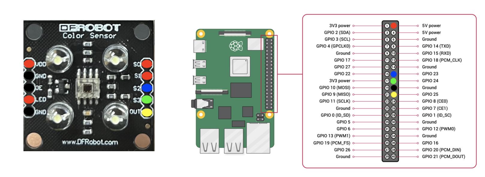
Using an L298 dual H-bridge, we connected 2 DC motors to the Raspberry Pi by modifying the stepper motor setup from previous projects. Additionally, battery packs were used to power the Pi and the DC motors through the H-bridge.
Coding
The coding process was rigorous and divided into three sections to control the line-following robot:
- Scanning Section: This scans RGB values of a line and maps the frequency values received to an RGB color.
- Control Section: This uses the scanned data and PID controls to update the motor speeds, allowing the robot to follow the line successfully.
- Motor Speed Adjustment: This updates motor speeds by reducing one motor's speed and increasing the other’s so the robot can continue detecting the specific color it needs.
The code works by detecting whether the color sensor reads a value closer to the specified color or white. If it reads white, the robot moves left; if it reads the specified color, the robot moves right.
The Solution
The video below shows the robot traversing through the blue line. The robot moves slowly due to overshooting issues that occur when the speed is increased. All challenges were completed, and the robot can traverse all 4 lines at different (slow) speeds, as well as go down one line, reset, and come back through any other line.